
Electricity is the flow of charge through a medium. Some materials are conductive, and charge flows through them easily, such as the copper in a wire or the lead-tin alloy that solder is made of. Other materials are insulative, such as rubber, and can block the flow of electricity. It helps to think of charge like water and wires as pipes.
Electricity is measured in multiple ways, but the main ones we care about are voltage and current. We will also use a measurement called resistance.
- Voltage is the electrical potential at a point in a circuit. When we make circuits, we care less about the voltage at a point and more about the difference between two voltages. If a point in a circuit were a bucket with the pipes connected to the bottom, voltage would be like the depth in the bucket.
- Current is the rate at which charge flows. Think of the current through a wire as being similar to the water pressure through a pipe.
- Resistance is how hard it is for charge to flow through something. Most wires have so little resistance that they effectively have none. We will use a component called a resistor that provides a set amount of resistance. Think of a resistor like a very thin pipe that restricts the flow.
These three values are related by a simple equation: V = I * R, where V is voltage, I is current, and R is resistance. Using this equation, as long as you know two, you can find the third. In most cases, you will know the voltage and the resistance, and need to figure out the current. Or, you will know the voltage, and need to achieve a specific current by choosing a resistance.
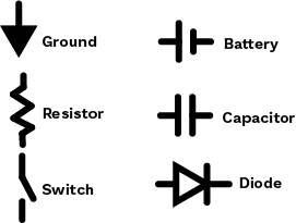
Circuits are drawn with a certain type of diagrams, which have their own sort of code. The diagram shows the six most common symbols: Ground (where the voltage is zero), the Battery (which creates a voltage), a Resistor (which provides resistance), a Capacitor (we’ll get to that later), a Switch (used to turn a circuit on or off, and a Diode (there are many types, the most common is an LED light).
One important thing to remember with circuits is the direction of flow. The charge flows from positive to negative, even though the actual electrons travel from negative to positive. Some components are polar, meaning their direction matters. Others are the same forwards as backwards.
Common Components
- Ground is where the voltage is zero. Because only the difference between voltages matters, ground is really just the point we are measuring against; it is our benchmark.
- A Battery generates a current by cycling electrons through a circuit, like a water pump but for electricity. The longer line indicates the positive end, and the shorter line indicates the negative end. Each battery will have a listed voltage. For example, an 8V battery would have 8 volts at the long line, and 0 volts at the short line. The charge is pumped the long way around the circuit, not directly across the battery, so it is essentially a ground and a power source.
- A Resistor limits the flow of charge. This is the main tool you will use to control the electricity.
- A Capacitor fills up with charge and then releases it, and is used to work with waves and signals.
- A Switch is a wire with a break in it and a means to close the break. In electrical terms, switch can mean an actual switch, or it can mean a button, dial, lever, or anything that can open and close a circuit.
- A Diode is a wire with a break, and the two unconnected ends a short distance apart in a chamber. The way they work is complicated; you’re encouraged to learn about other types, but we will only use one: the Light-Emitting Diode, or LED. An LED lights up as current passes through it, but only if the current goes the proper direction: otherwise, it will overheat and can explode.
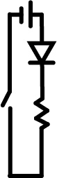
This diagram is a simple circuit. The battery at the top pumps current to the right, where it goes down through the LED, through the resistor, and back up through the switch to the other end of the battery. This is a basic light. The LED creates light when given current, the battery provides power and creates that current, and the switch is there so it can be turned on and off.
Why is the resistor there? Remember that V = I * R. The battery provides us with a fixed V, and the LED requires a specific I. Current must be the same the whole way through a wire, because there is no new charge being added or removed. Therefore, the current going through the LED is the same as the current going through the resistor. By using our equation and choosing R carefully, we can achieve a specific I with a fixed V.
Adding the resistor in this way gives us control over the current passing through the diode, which is important. If we sent too little current, it would either be too dim or not turn on. If we sent too much current, it might kill the LED.
These components will get you through most basic electrical operations. It’s easy to add other types of switch or other types of diode to get different effects or types of user input. Research on your own, take an electronics class, or ask an Explorer for help.
Multiple Resistors
Resistors can be used together to either increase or decrease the resistance, giving you more control over your chosen resistance values.
- More Resistance: Resistors in series, meaning in a row, will add their resistances. If a 100Ω resistor is followed by a 200Ω resistor, they will together act like a 300Ω resistor.
- Less Resistance: Two resistors in parallel, meaning they are joined to each other at each end, diverting the current through them, combine differently. Their combined resistance is the reciprocal of the sum of their individual reciprocals. The reciprocal of a number is 1 divided by that number. If a 100Ω and a 200Ω resistor are in parallel, they will have a net resistance of only 67Ω, found using this math:

Multiple Capacitors
- Capacitors can be combined in a similar way to resistors, but their capacitances combine according to the reverse math.
- Capacitors in parallel add their capacitances directly.
- Capacitors in series add their capacitances according to the reciprocal law that also applies to resistors in parallel.
Branching Circuits
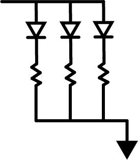
Not all circuits form one clean line from power to ground. In many cases, you may see something like the circuit above, where one wire branches into several before merging back together. In a circumstance like this, the same rules apply regarding voltage and resistance, but current will act slightly differently: the current is not the same at every point, but the total current is. Therefore, the current at the start is the same as the current at the end, and is the same as the sum of the current from the three branches.
If all three branches were exactly the same, the same current would flow through each one. If the resistors on each of the three were different, the three currents would be as well. Remember that V = I * R. The voltage drop will be the same across each of the three branches, since they are all connected to the power source at the top and to ground at the bottom. Since we know the voltage for each one, if we know one of the resistor values we can find the current through that branch by doing I = V / R.
Assuming we know all three resistor values, we can know the current going through each of the branches. Since total current is the same at every point, we can add up the three currents in the branches to find the current before they branch, and the current after they recombine.