Fusion 360 is a collaborative computer-aided design (CAD) software. Unlike some other CAD software, Fusion makes it easy to share your projects with other people. There are many other CAD softwares out there, but Fusion is quite commonly used and very easy to learn.
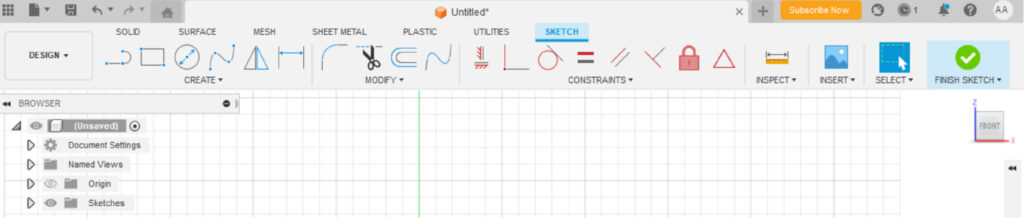
Sketch Planes
A sketch plane is exactly what it sounds like: the plane on which you draw your sketch. When starting out with a blank canvas, you can choose the plane that you’re drawing on: front, back, or side. Once you start building a part, you can define planes based on your part.
Sketches and Lines
A sketch is a 2-dimensional drawing. Sketches can be as complex or as basic as you want them to be! The “sketch” tab contains a section where you can choose lines, curves, circles, rectangles, slots, and more. There are two types of lines that your sketch can be composed of:
- Lines: These are the lines you can do other things with, such as extruding them when these lines create a closed shape (more on that in the Bodies section).
- Construction lines: These lines are meant for construction only. They can help you define dimensions and other parameters (more on that in the Dimensions section).
Tip: Make it a habit to start your sketch on the origin. This anchors your sketch in a 3D space, and will give you one less variable to worry about.
Dimensions, Constraints and Defined Sketches
It is important to note that you should always define your sketches. You can do this by setting dimensions of your sketches with the “d” key. Dimensions can include lengths of lines, distances, angles and radii.
You can also set constraints (some CAD software call this function “relationships”) in addition to setting dimensions. Constraints make it easier to change multiple dimensions at once, since you relate dimensions to a base dimension. Constraints include making two lines parallel, equal or perpendicular, making two shapes co-centric, making a shape and a line tangent to each other, and more!
While you don’t have to use constraints (you could just define everything individually), you should. It will make your CAD project much, much easier to work with. Depending on what sketch function you use, you may have constraints already (ex: using the rectangle sketch tool will always use parallel lines and equal, right angles).
A defined sketch is one where every possible dimension and constraints is defined. While you don’t ever have to define a sketch, it is always in your best interest to. This is because an undefined sketch can get messed up if you try to change a feature later down the road. Defining everything properly is a good habit to build.
An over-defined/driven sketch is where you already had every possible dimension/relationship defined, and tried to add another dimension/relationship. This will give you an error message, and you will have two possible options: to either create the dimension/relationship that gave you the error (and risk messing up other parts of your sketch) or to leave it as is.
The photos below show a sketch of a square.
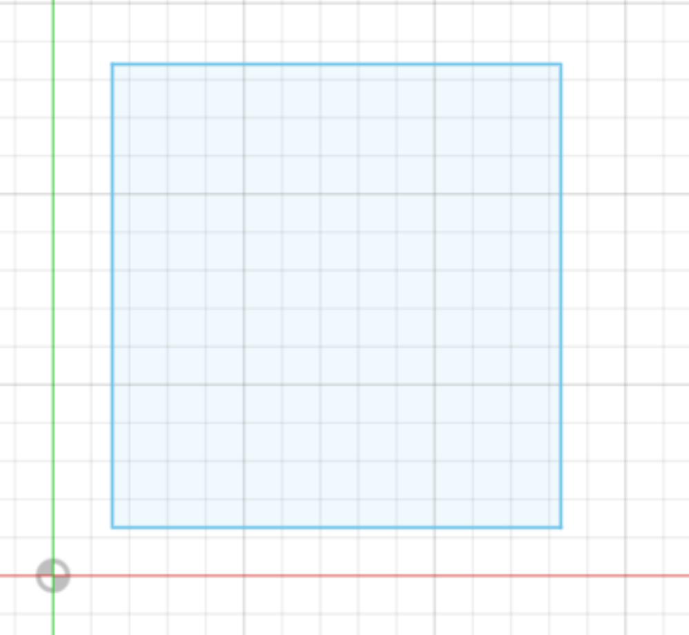
This sketch is undefined. It is missing key information: how big is the square? Where on the plane is the square? Is it even a square? We don’t know because we aren’t sure of the dimensions of each side, or if those are even 90 degree angles. Note that the lines that form the square are blue: that means that it is undefined.
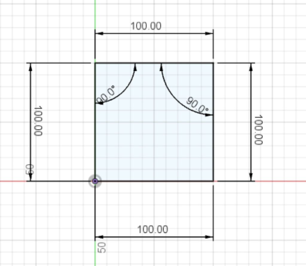
The second sketch is defined, but not according to best practices. The square has each side’s dimensions set to 100mm manually. The bottom left corner anchors the sketch in space. This was done by selecting the bottom point and the “coincident” constraint.
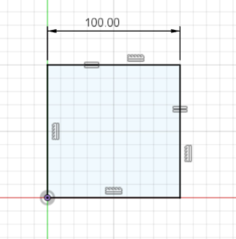
This last sketch is properly defined, according to best practices. Note that only one length the square is given a dimension, and that all the other sides have “vertical”, “horizontal”, and “equal” constraints. The vertical/horizontal constraints tell us that this square has only right angles. The equal constraints tell us that we have a square and not a rectangle.
Tip: The “lock to grid” feature in Fusion 360 makes it easier to automatically set constraints. Note the light grey grid in the above sketches. You can have your sketches snap to this grid, which will often automatically set constraints, such as vertical and horizontal lines. Whether you turn this feature on or off is up to you—automatically setting relationships may be a nuisance depending on the sketch you’re making.
Sketches to Bodies
There are many different operations to make your 2D sketch into a 3D body. Here we will go over three of the most basic ones: Extrude, revolve, and extrude cut. All of these three require closed sketches. This means your sketch cannot be a series of disconnected lines.
Extrude
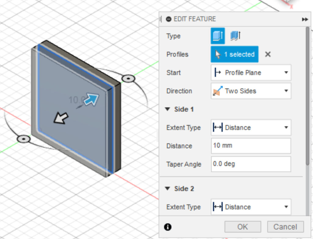
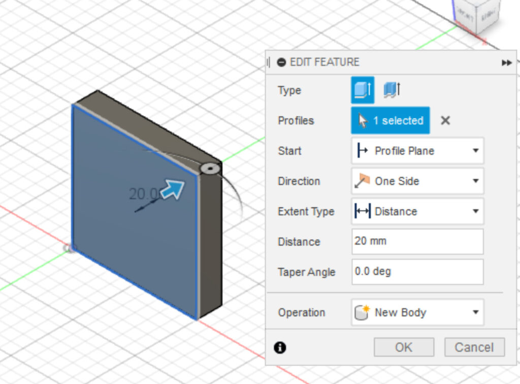
Extrude is the most basic of all operations. It gives depth to your 2D sketch. You must choose which direction your sketch will extrude, and to what extent it will. Below are two versions of our square sketch. One is extruded 20mm in the Y direction. The other is extruded 10mm in the positive Y direction and 10 mm in the negative Y direction. Both version will give you the exact same body (a 100mm x 100mm x 20mm body) but located in different directions in space.
Revolve
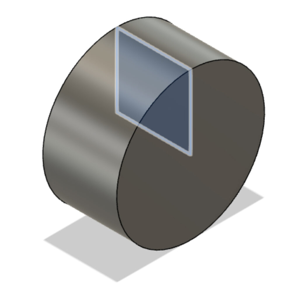
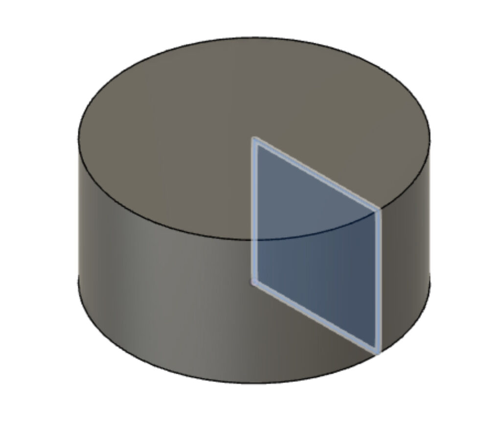
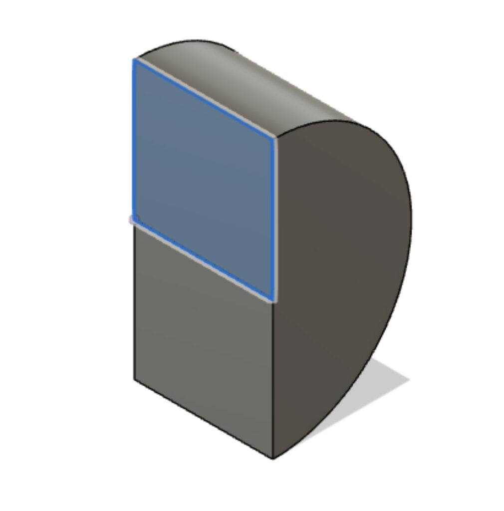
Revolve is how you make rounded objects. To revolve a sketch, you must define two things: the axis of rotation and the degree to which you rotate it. Below are three versions of our square: a 360 revolution around the Y axis, a 360 revolution around the Z axis, and a 180 revolution around the Y axis.
Extrude-Cut
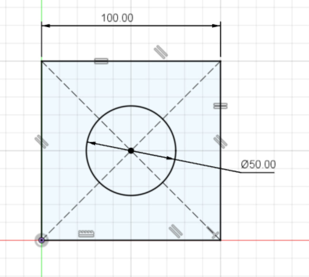
Extrude cut requires a bit more sketching. Now, we have two shapes in our sketch: the original square, and a circle within the square. Note that our original sketch is a little different and has dotted lines: those are construction lines. Those lines help with dimensioning and constraining the sketch only, so you cannot extrude/extrude-cut them. Here, those construction lines help define the center of our square, making it easy to place our circle’s center perfectly in the square’s center.
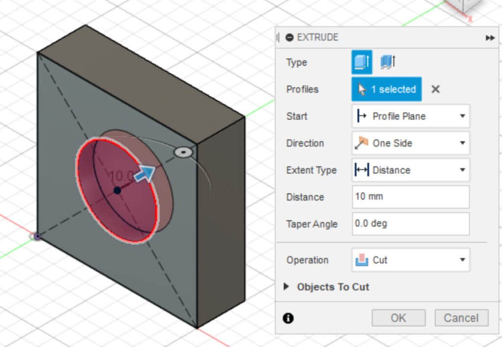
We’ve extruded the original sketch 30mm in the Y direction. Now, we can select the circle and cut out its profile in the Y direction. Just like the extrude operation, we must define our direction and depth. The difference here is that we are taking away material, rather than creating it.
General Best Practices
It’s important to build out good habits now at the beginning of your CAD journey. These are some best practices: optional, but will save your future self from headaches.
- Fully define your sketches before you turn them to bodies. It’s easy to overlook this step, but the more complex your sketches become, the harder it will be to backtrack and fix dimensions after you’ve turned them into bodies.
- Name your sketches, bodies, and operations. Fusion will automatically name your sketches, bodies, and operation in the order in which you create them (I.e. Sketch 1, Sketch 2, Body 1) but this gets confusing the more you build on a design. Name your sketches/bodies for what they are when you’re fabricating.
- Use constraints/relationships as much as possible.