This document will walk you through the basics of making flat pack dinosaur skeletons using the laser cutter. Text in black explains certain concepts.
Text in blue boxes are steps you should actively be taking to practice these skills.
Prerequisites:
Safety Considerations
Resources:
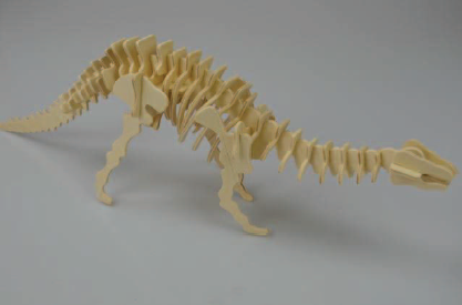
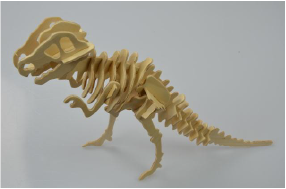
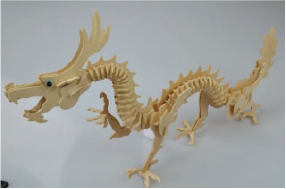
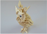
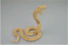
Choose one of these Dinosaur skeletons. – The links in the captions point to the PDFs of the instructions. Download the instructions with the cutting diagrams included.

Setup
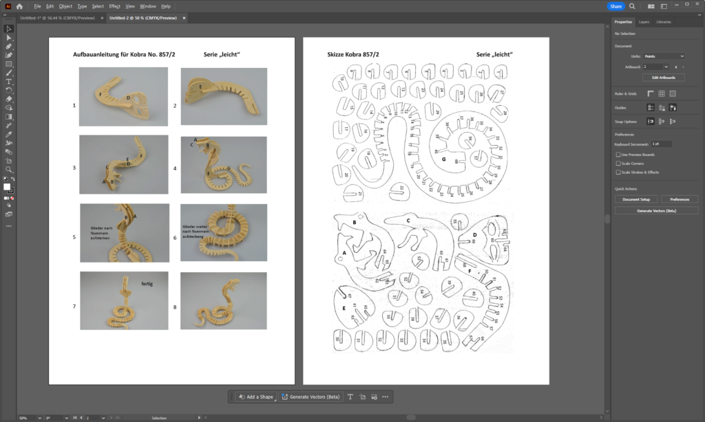
Open the PDF instructions for your chosen model in Illustrator.
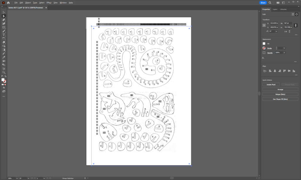
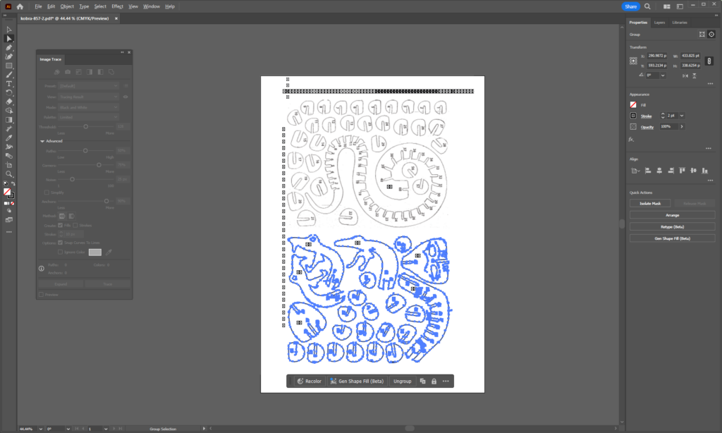
Select the page with the outlines of the parts, and do an image trace. Window – Image Trace will bring up the image trace menu. Play with the image trace settings to get as close to complete paths as you can. It may not make a perfect trace, but you’re going to edit it in CAD soon anyway.
Hit Expand at the bottom of the Image trace window to convert to paths.
While the expanded Selection is still highlighted – or reselect them if you need to – export that selection to a .dxf. That’s a format that works well with CAD software. use File – Export – Export As and choose .dxf as the output format.
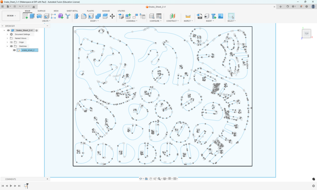
Open a new Fusion 360 File and choose Insert – Insert DXF. Add the file you just exported from Illustrator.

The image trace output will now appear as a sketch in Fusion 360.
Now you’ll need to scale and clean up the sketch. You need a few important pieces of information:
- The size of the stock you want to use.
- The thickness (actual thickness – measure it with calipers!) of the stock you want to use.
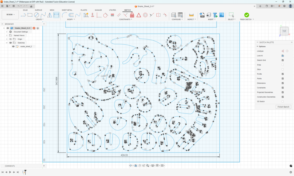
First, measure the rectangle around your paths. Start editing the sketch by selecting it in the design browser ribbon on the left or the timeline across the bottom of the screen. Then use the Dimension command to measure the rectangle.
Use Modify-Sketch Scale to scale the sketch to fit your material envelope. This example will fit the material envelope to 24″x 12″ for our typical laser cutting stock.
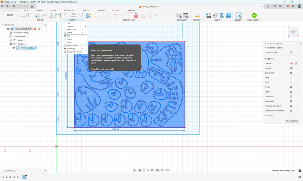
The Scale command will accept a fraction, so choose either the height or width of the rectangle and enter the fraction [desired size] / [measured size in your sketch].

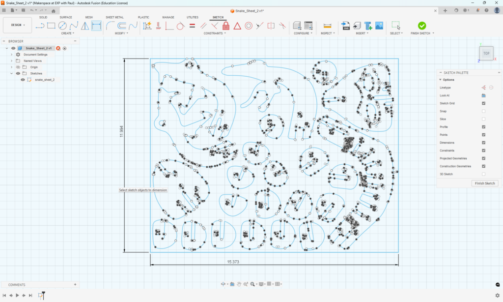
After scaling, you may need to zoom in or out a lot. Double check the size of your sketch to verify that it will fit in your material envelope.
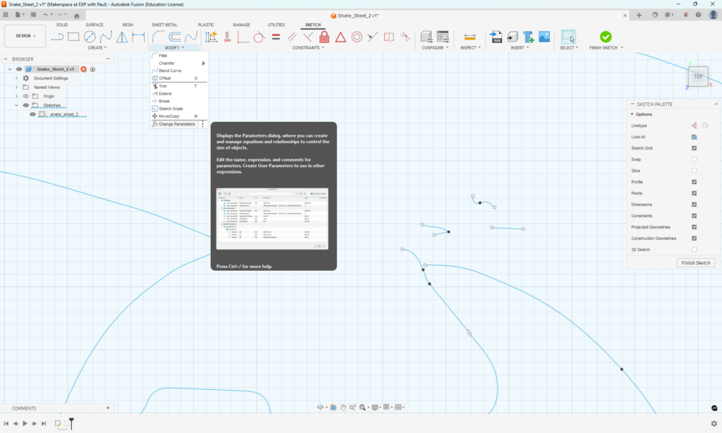
Now, it’s time to clean up the path so that they make complete loops without a lot of stray line segments. While doing that, you can also change the slot widths to be equal to your material thickness. Work around each outline using the Extend and Trim commands to make each piece a complete loop. Make the width of each slot where the pieces go together the thickness of your material. Make a parameter for that thickness using the Modify – Change Parameters.
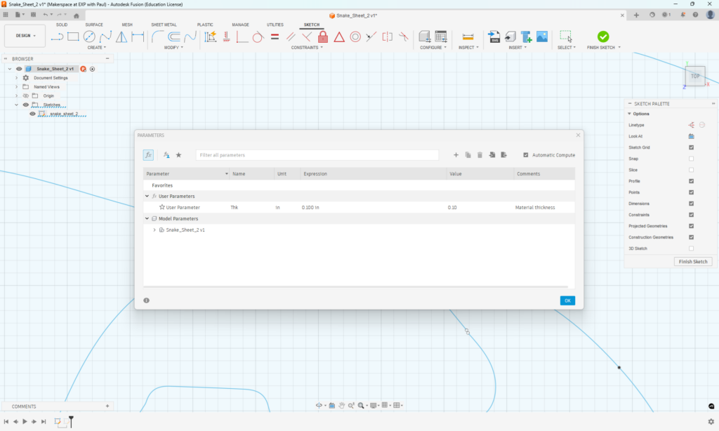
Create a user parameter and set it equal to the material thickness.
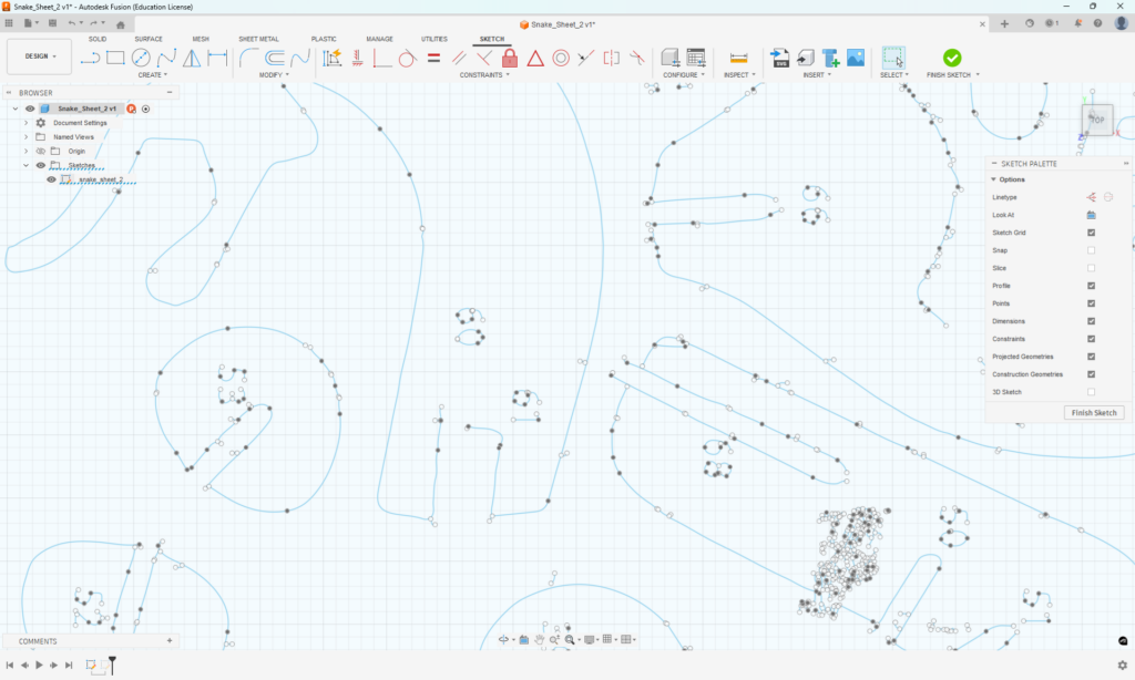
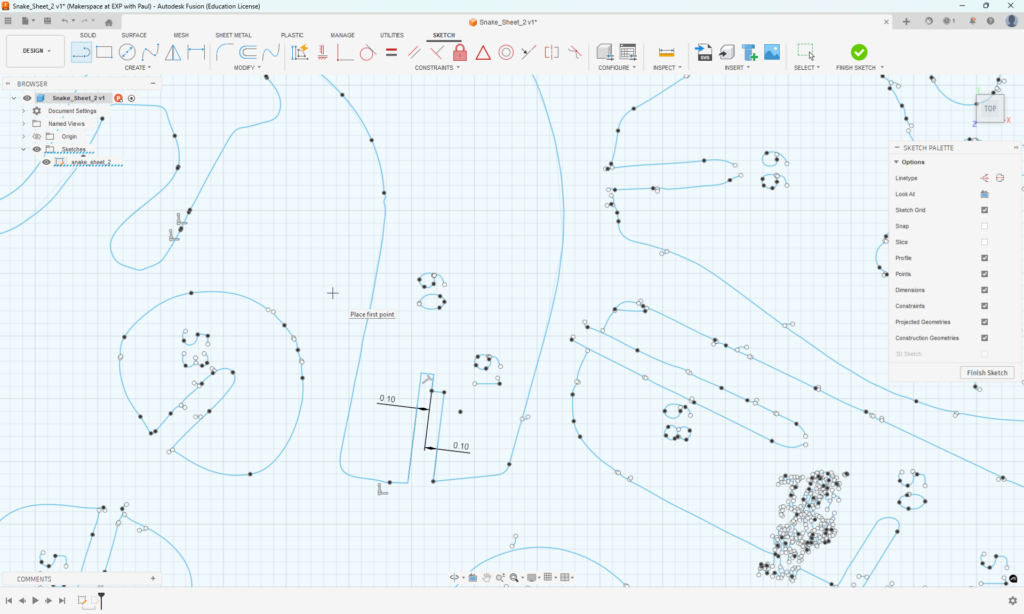
Edit the sketch so that the outlines have assembly slots that are parallel, with widths equal to the parameters that you just set. In this example, the slot take two pieces of material. You may need to reference the original image to make sure the shape will fit correctly.
Before:
After:
Clean up every piece, export your sketch as a DXF, and cut it out with the laser cutter. Put together a new dinosaur skeleton! – The steps here are intentionally left out – it’s a challenge!